Hi. Thanks for Visiting!
In a nutshell, I provide prototyping services applying expertise in single board computers, sensors, actuators, hardware/software design and fabrication throughout the complete product design process.
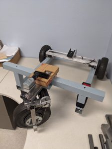
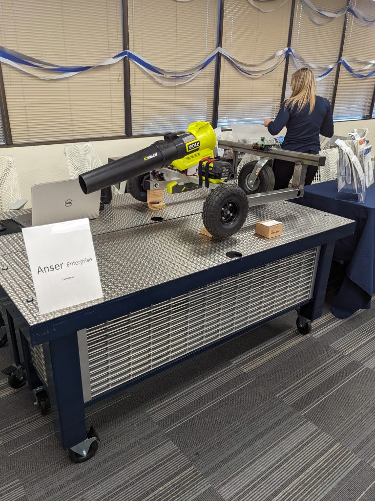
Also, I’m building several autonomous guided vehicles (AGV) and blogging on their progress as frequently as possible to share ideas and solicit feedback.
Available Q1 26
AGV Blog
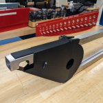
- Sprocket Mounting Hub (Weld on)
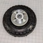 I designed a new sprocket hub that allows a 55 tooth #25 chain sprocket to attached to a 10″ pneumatic tire wheel. The sprocket hub’s design allows it to be welded onto the the end of the wheel’s 1.5″ rim… Read more: Sprocket Mounting Hub (Weld on)
 - Sprocket Mounting Hub (Removable)
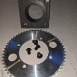 This describes the design and fabricated of a sprocket hub with the primary advantage of easy attachment and axial adjustment on 1.5″ OD wheel rim hubs. Materials used consist of 1.5″ ID, 1/8″ wall steel tubing (DOM) for the hub… Read more: Sprocket Mounting Hub (Removable)
 - Rear Chain Guard Re-Design
 I changed the design of the rear sprocket guards and 3D printed them. The front half-circular guard section required no changes since I can insert and remove it easily by turning it 90 degrees, sliding it between the top and… Read more: Rear Chain Guard Re-Design
 - Chain Guard Design
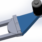 I’m reviewing 3D Printed guards designed to protect #25 chains and sprockets. A primary constraint in their design is that they need to be the last components easily added (and removed), completing a vehicle’s assembly. Easy access for adjusting the… Read more: Chain Guard Design
 - Welding Jigs for Parallelism of Four Corner Vertical Frame Tubing
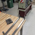 Issue: The four wheeled AGV frame consists of machined horizontal and vertical 1″ x 1″ 16 gauge steel tubing pieces welding together. In addition the vehicle platform has four vertical 7/8″ x 7/8″ x 3″ tubing stubs at the platform’s… Read more: Welding Jigs for Parallelism of Four Corner Vertical Frame Tubing
 - Controller, Printed Circuit Board, and Wiring Details
 Using EasyEDA PCB Design Software, I previously designed and ordered 100×100 mm printed circuit boards from JLCPCB. Also, I designed a 6″x4″x2″ acrylic PCB enclosure using SolidWorks and LaserCAD software and cut the enclosure sides from .118″ clear acrylic sheets using a BOSS… Read more: Controller, Printed Circuit Board, and Wiring Details
 - CNC Machining Top Frame Tubing
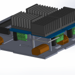
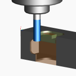 The tank-driven four wheel driven AGV is fabricated primarily from 16 gauge 1″x1″ square steel tubing, which is machined manually or on Tormach PCNC 1100 Mill and Tormach 15L Pro-Slant CNC Lathe machines. Presented here are machining configurations and operations… Read more: CNC Machining Top Frame Tubing
 - Four Wheel Chain Drive vs. Direct Drive DecisionThe choice of mechanical drives depends on the application and other factors. See below: AI Overview For a four-wheel robot, the better drive system depends on your specific needs for power, precision, and maintenance. A direct drive is simpler, more efficient,… Read more: Four Wheel Chain Drive vs. Direct Drive Decision
We provide an array of Resources
A comprehensive suite of professional services with access to top notch development, fabrication and testing facilities including
- Electronic design software
- Printed Circuit Board fabrication
- Laser CNC fabrication
- 3D Printing
- CNC and manual lathe and mills