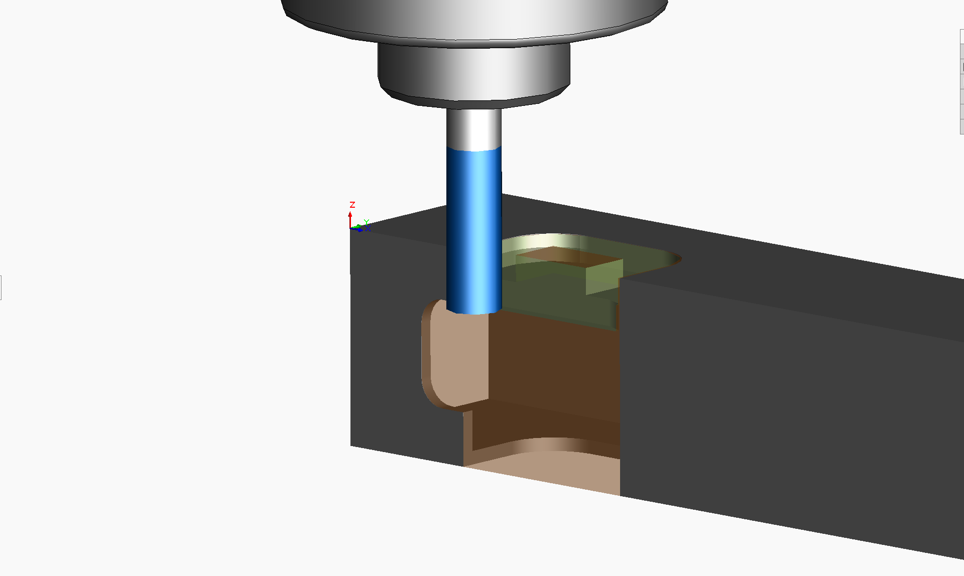
The tank-driven four wheel driven AGV is fabricated primarily from 16 gauge 1″x1″ square steel tubing, which is machined manually or on Tormach PCNC 1100 Mill and Tormach 15L Pro-Slant CNC Lathe machines. Presented here are machining configurations and operations generated in SolidWorks CAM software. This image shows CAD features to be machined in one of the frame components.

For this part, I stepped though a series of SolidWorks CAM software definitions/configurations such as Define Machine, Coordinate System, Stock Manager, Mill Setup. For Coordinate System, I oriented the Z-direction such that a 1/4″ end mill could be programmed to plunge down and machine out a complete U-shaped pass through for the motor shaft, sprocket pinion and encoder. The X-axis is along the length of the tubing and the Y-axis is along the tubing’s 1″ cross section.
Mill Part Setup 1 is defined to be an Open Pocket (Rough-Finish) operation. Using the SolidWorks CAM 2.5 Axis Feature: Select Entities dialog I specified the sketch to use for the feature profile to machine, an End condition of 1.10″ to machine through both sides of the tubing, a 2.5 Axis Feature Type: Open Pocket, Strategy: Rough-Feature.
Using the ‘Generate Operation Plan’ command, I created the machining operations for the machinable features, based on rules defined in SolidWorks Technology Database. Both Rough Mill and Contour Mill with 0.25″ Flat End operations were produced for the Open Pocket.
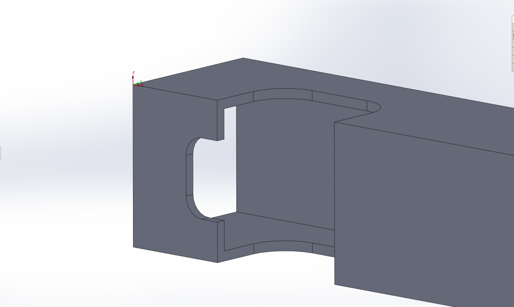
Using the ‘Generate Toolpath’ command, the CAM software produced the tool path movements highlighted in light green in this image.

Next, the ‘Simulate Toolpath’ command is used to animate the end mill moving according to the toolpath above.

Finally, the ‘Post Process’ command is used to generate the G Code that is transferred to the CNC Mill.
Looking down on the top frame held on its side on the mill table, notice that the toolpath in the image below starts at Y: -0.06” outside the tubing. Therefore when it plunges down, the center of the 4 flute ¼” end mill is not forced into the material, necessary because it has no drilling action at its center.
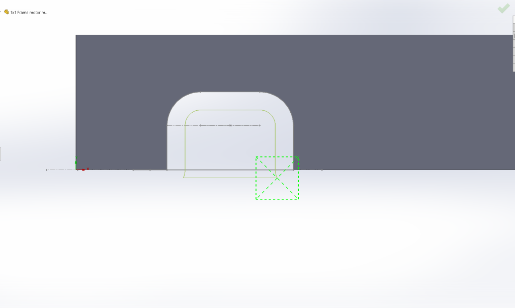
Also, see in the toolpath outside the material above and in this G Code segment below that there are G03 circular interpolation commands implementing the lead-in and lead-out parameters. This defines how the side of the end mill enters and exits the material.
O0001
N1 G20
N2 (1/4 EM HSS 4FL 3/4 LOC)
N3 G91 G28 X0 Y0 Z0
N4 T20 M06
N5 S1252 M03
N6 ( Rough Mill1 )
N7 G90 G54 G00 X1.493 Y-.06
N8 G43 Z.1 H20 M08
N9 G01 Z-.125 F1.2529
N10 G17 X.7959 F5.0115
N11 G03 X.81 Y0 I-.1209 J.06
N12 G01 Y.329
N13 G02 X.925 Y.444 I.115 J0
N14 G01 X1.3639
N15 G02 X1.4789 Y.329 I0 J-.115
N16 G01 Y0
N17 G03 X1.493 Y-.06 I.135 J0
N18 G00 Z.1
Leave a Reply