Using EasyEDA PCB Design Software, I previously designed and ordered 100×100 mm printed circuit boards from JLCPCB. Also, I designed a 6″x4″x2″ acrylic PCB enclosure using SolidWorks and LaserCAD software and cut the enclosure sides from .118″ clear acrylic sheets using a BOSS Laser HP3655. After soldering all the electronic components onto the PCB the task remained to neatly route the 14 gauge wiring coming in from the battery and going from the BTS7960 motor driver modules to the 100 watt 12V MY6812 DC motors. I used SolidWorks again to create a 3D model of the PCB enclosure base with the PCB mounted on standoffs, 12V to 5V buck convertor, and WAGO lever wire connectors primarily for the 14 gauge wiring.
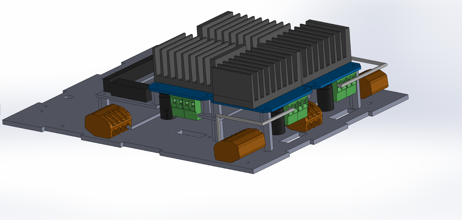
Here is an image of the PCB Enclosure SolidWorks model showing battery GND wiring from the orange WAGO lever nut connectors to the green B- screw terminal ports of the four BTS7060 motor driver modules.
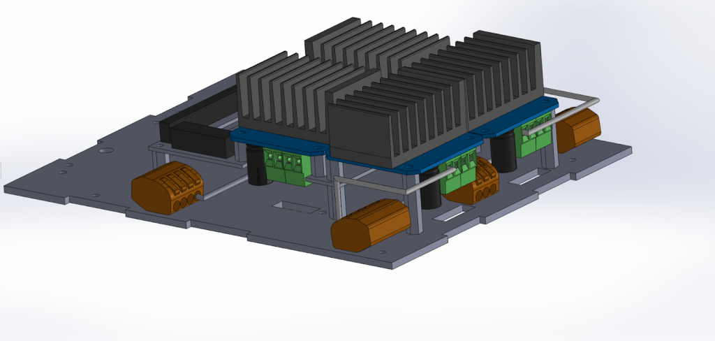
The point of the visualization is to accurately determine the lengths of the wire segments between bends, bend directions and optimized wire routing given the compact design of the PCB. A remaining manufacturability task is to fabricate wiring jigs to form the wiring shapes efficiently.
Leave a Reply