This describes the design and fabricated of a sprocket hub with the primary advantage of easy attachment and axial adjustment on 1.5″ OD wheel rim hubs. Materials used consist of 1.5″ ID, 1/8″ wall steel tubing (DOM) for the hub collars, 2 hub collar set screws securing it to the wheel rim hub and 3/16″ thick 2″ steel squares used for the sprocket hub plates each with 4 threaded screw holes to mount the sprocket. Fabrication operations include
- Drilling/tapping set screw holes through perpendicular planes in the steel tubing sides
- Lathe parting 1″ long collars from the steel tubing stock ensuring their ends were square, required for the hub plate welding
- Cutting 2″ squares from the 3/16″ thick, 2″ wide rectangular bar stock
- Clamping and welding the steel squares perpendicularly to the ends of the hub collars.
- Lathe facing a 1/16″ boss registration feature matching the sprocket ID to ensure concentricity of the sprocket and collar.
- Boring the inside of the hub collar to achieve a good fit to the wheel rim hub.
- CNC/manual mill drilling/tapping 4 sprocket mounting screw holes at the corners of the squares.
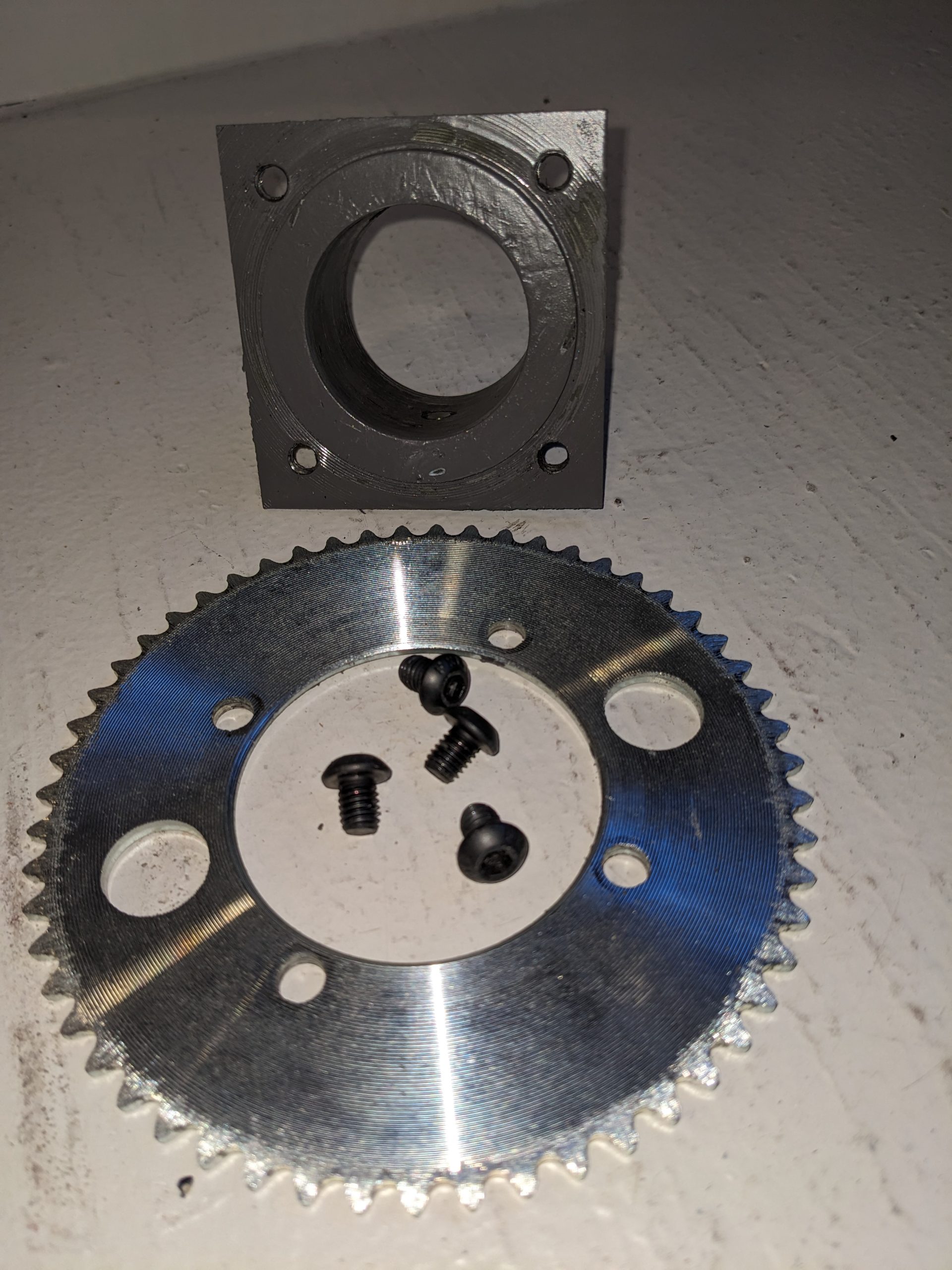
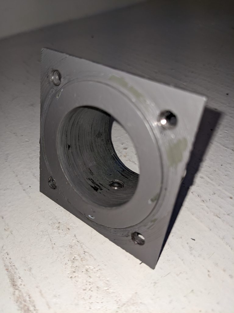
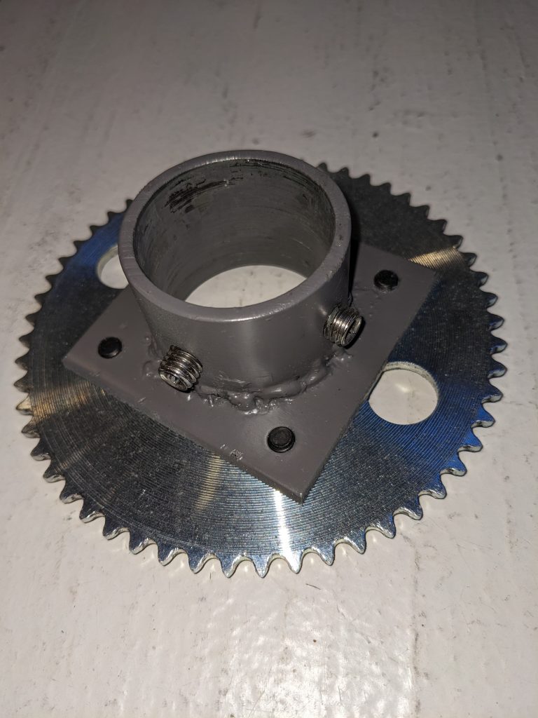
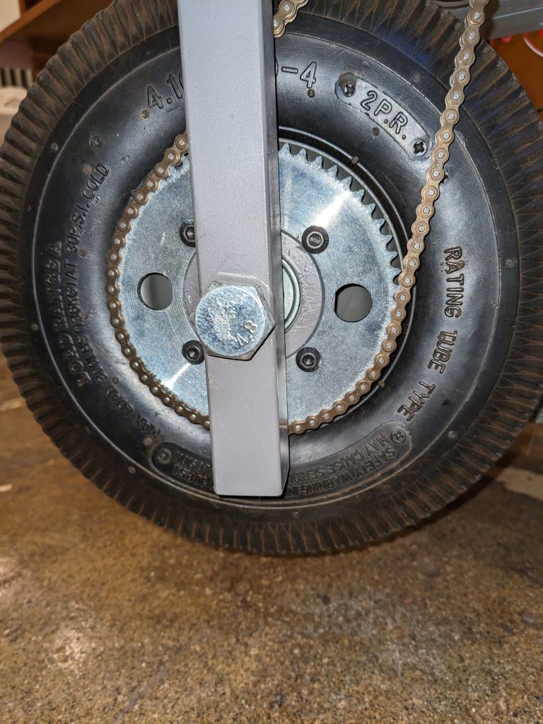
Here are images of the sprocket hub and assemblies with the 10″ pneumatic tire wheel and 55 tooth #25 chain sprocket.

Leave a Reply